7820 Dinmore Manor - The Blog
This blog will follow the heavy overhaul of 7820 through to its return to steam. The chassis is being overhauled at Tyseley Locomotive Works whilst the boiler is being overhauled at Ian Riley's workshops.
We are working hard every weekend to bring together the hundreds of small pieces that require refurbishing to get the loco back into working order. Follow us to keep up todate with the weekly progress and who knows if you like the look of what you see you may even be tempted to join us and help put 7820 back in action.
We are working hard every weekend to bring together the hundreds of small pieces that require refurbishing to get the loco back into working order. Follow us to keep up todate with the weekly progress and who knows if you like the look of what you see you may even be tempted to join us and help put 7820 back in action.
Sunday, 27 January 2013
Refitting of Drain Cocks 26.01.13
The firemans side cylinder and steam chest drain cocks refitted to the mounting plate and assembled to the cylinder mounting studs. The operating rod and pushers have been added after mounting of the drain cocks
Monday, 21 January 2013
More parts undergo refurbishment.
The first parts of the refurbished cylinder cladding are fitted before the bogie goes back in.
The coupling rods have been dug out of storage and are being cleaned off.
New felt pads being cut for all of the lubrication points.
Main steam fountain cleaned down ready for inspection of all threads and seats new packing for all the spindles will also be installed.
A start is made of refitting the slide bars.
Slide bars in place ready for measuring which in turn will allow machining of the cross head white metal.
The quadrant (expansion) links are cleaned and having been ground and fitted with remetalled die blocks are prepared for paint prior to installation.
The repainted fire iron tunnel is now resting back in place on the frames.
More parts lurking in the container, some ready for fitting some still requireing attention.
Refitting the weighbar shaft.
The following set of photos show the installation of the weighbar shaft into the frames and represent the start of the installation of all the valve motion.
First job to make sure the bushes are spot on and the grease will be distributed along the shaft where it is required.
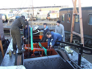
With the bearings on the ends of the shaft everything is suspended from the gantry and lowered into the holes in the frames.
One end is slid right through the frame hole to allow the opposing end to drop down inside the frames.
The entire aseembly is then slid back to centarlise it in the frames.
Lastly a bit of final adjustment to get the fitted bolts into the frames and the locking rings secured on the shaft.
Saturday, 19 January 2013
Subscribe to:
Comments (Atom)


